If you are in charge of an operational subway/high-speed rail tunnel automated monitoring project that requires regular monitoring of the tracks and tunnel segments, then the method and equipment described in this article for synchronizing track measurement and tunnel scanning will play a significant role in helping you reduce costs and improve the efficiency of project implementation.
1. Pre-operation preparation
1.1. Work equipment
The Tunnel Full-Section Geometry Inspection Instrument (AIS800S) is composed of the following two main modules:
Scanners: Z+F, Faro, Leica, Sick, etc.;
Inertial Navigation Track Measuring Instrument: Gauge, Superelevation, Level, Alignment, Vertical Alignment, Directrix, Twist (Triangular Pit), Gauge Variation Rate, Deviations of the track centerline and the left and right rails from the designed track shape in the plane (lateral) and elevation (vertical) directions, and other geometric parameters of track size and shape.
1.2. Personnel on Duty
Surveyor: Proficient in operating equipment and well-versed in safety management regulations for on-track operations.
Auxiliary Surveyor: Clearly understand the scope of work, assist in recording the measurement process, and be familiar with safety management regulations for on-track operations.
Safety Officer: Familiar with safety management regulations for on-track operations, responsible for the safety of personnel and equipment.
1.3. Essential Documentation
Line Design Records: Horizontal Curves, Grade Table, Break Table.
Scope of Work: Accurate mileage of the start and end points for track measurement (scanning).
2. Data Collection Operation
(1) Equipment Assembly;
(2) Push to the Starting Point of the Operation;
(3) Equipment Initialization: 300 seconds;
(4) Begin Measurement;
(5) Push to the End Point of the Operation: 3 km/h;
(6) End Measurement;
(7) Operation Completed.
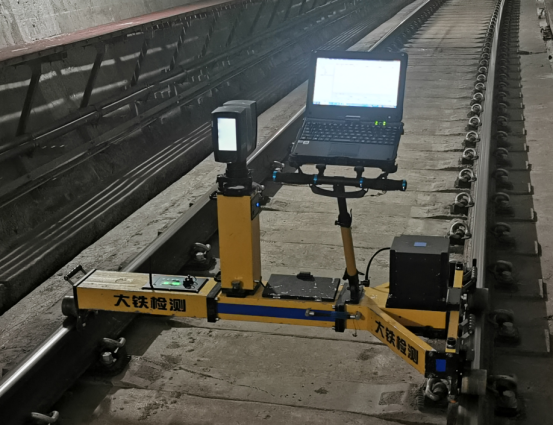
Figure 1 Tunnel Full-Section Geometry Inspection Instrument(AIS800S)
3. Data Processing
Specialized data processing software is used to complete post-processing of the operational data, ensuring the accuracy and reliability of the data. For tunnel scanning data and track measurement data, they are processed independently, and advanced data fusion techniques are applied to integrate the results of both, thereby forming a complete and accurate final report. This approach better integrates data resources, improves the efficiency and precision of data processing, and provides strong support for the smooth implementation of the project.
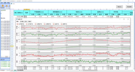
Figure 2 Track Measurement Data Processing 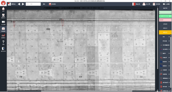
Figure 3 Tunnel Scanning Data Processing
4. Results Output
Based on project requirements, output the corresponding result reports. The track measurement results are mainly presented in reports and graphics, including measurement mileage, gauge, level (superelevation), alignment, vertical alignment, directrix, twist (triangular pit), gauge variation rate, and the planar (lateral) and vertical (elevation) deviations of the track centerline and left and right rails relative to the track design shape. The tunnel scanning results are also primarily in the form of reports and graphics, with main content including: tunnel unfolded diagrams, defect unfolded diagrams, cross-section parameter tables, defect detail tables, cross-section shape diagrams, and schematic diagrams of defect locations.
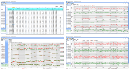
Figure 4 Track Measurement Results Display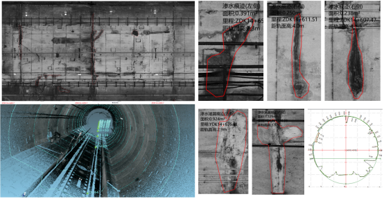 Figure 5 Tunnel Scanning Results Presentation
5. Summary
The Tunnel Full-Section Geometry Inspection Instrument completes continuous moving tunnel scanning while performing high-precision track measurement operations, which enhances the overall work efficiency. Conducting track measurement and tunnel scanning simultaneously ensures the consistency of the two sets of measurement data, avoiding issues with data inconsistency. Syncing both processes helps avoid the waste of human and equipment resources, making it more economical and efficient.